Aerospace Toolbox provides the ability to model and visualize satellites in orbit, compute access
with ground stations, visualize and analyze communication links using the satelliteScenario
object. This topic provides an overview of the technical terms frequently encountered in
scenario visualization.
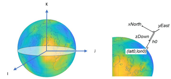
A geodetic system uses the coordinates (lat,lon,h) to represent position relative to a reference ellipsoid. All geodetic coordinates in satellite scenario use the WGS84 ellipsoid as the reference ellipsoid. The coordinate origin of WGS 84 is meant to be located at the Earth's center of mass.
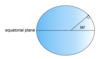
lat, the latitude, originates at the equator. More specifically, the latitude of a point is the angle a normal to the ellipsoid at that point makes with the equatorial plane, which contains the center and equator of the ellipsoid. An angle of latitude is within the range [–90°, 90°]. Positive latitudes correspond to north and negative latitudes correspond to south.
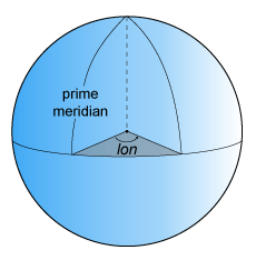
lon, the longitude, originates at the prime meridian. More specifically, the longitude of a point is the angle that a plane containing the ellipsoid center and the meridian containing that point makes with the plane containing the ellipsoid center and prime meridian. Positive longitudes are measured in a counterclockwise direction from a vantage point above the North Pole. Typically, longitude is within the range [–180°, 180°] or [0°, 360°].
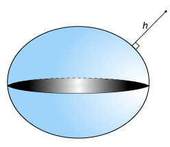
h, the ellipsoidal height, is measured along a normal of the reference spheroid.
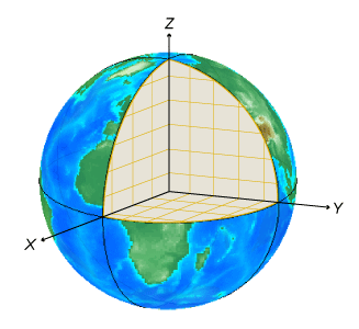
An Earth-centered Earth-fixed (ECEF) system uses the Cartesian coordinates (X,Y,Z) to represent position relative to the center of the reference ellipsoid. The distance between the center of the ellipsoid and the center of the Earth depends on the reference ellipsoid.
The positive X-axis intersects the surface of the ellipsoid at 0° latitude and 0° longitude, where the equator meets the prime meridian.
The positive Y-axis intersects the surface of the ellipsoid at 0° latitude and 90° longitude.
The positive Z-axis intersects the surface of the ellipsoid at 90° latitude and 0° longitude, the North Pole.
[1]
To describe a point in space, you need a frame of reference that does not rotate with
respect to the stars. The Geocentric Celestial Reference Frame
(GCRF), with the origin at the Earth’s center and orthogonal vectors
I, J, and K, is used as frame of reference while adding satellite
objects to satelliteScenario. The fundamental plane is the I, J plane, which is closely aligned with
the equator with a small offset, and K aligns closely
with the north pole. You can describe the location of a satellite using a position vector
and a velocity vector in the geocentric-equatorial coordinate system.
When referring to a satellites position, velocity, acceleration, orientation and angular velocity, the coordinate system in which they are expressed should always be mentioned. Global systems such as GCRF and geodetic systems describe the position of an object using a triplet of coordinates. Local systems such as NED, and AER systems require two triplets of coordinates: one triplet describes the location of the origin, and the other triplet describes the location of the object with respect to the origin.
A north-east-down (NED) system uses the Cartesian coordinates (xNorth,yEast,zDown) to represent position relative to a local origin. The local origin is described by the geodetic coordinates (lat0,lon0,h0). Typically, the local origin of an NED system is above the surface of the Earth.
The positive xNorth-axis points north along the meridian of longitude containing lon0.
The positive yEast-axis points east along the parallel of latitude containing lat0.
The positive zDown-axis points downward along the ellipsoid normal.
An NED coordinate system is commonly used to specify location relative to a moving satellite. Note that the coordinates are not fixed to the frame of the satellite.
Three lines run through a satellite and intersect at right angles at the satellite's center of mass. These axes move with the satellite and rotate relative to the Earth along with the craft.
Rotation around the front-to-back axis is called roll.
Rotation around the side-to-side axis is called pitch.
Rotation around the vertical axis is called yaw.
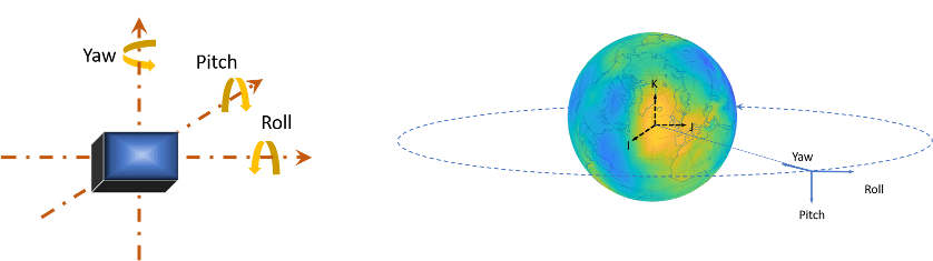
The yaw, pitch, and roll angles of satellites follow an ISO convention. These angles have positive clockwise directions when looking in the positive direction of the axes. Unless otherwise specified, by default Aerospace Toolbox uses yaw-pitch-roll rotation order for these angles.
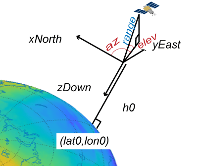
An azimuth-elevation-range (AER) system uses the spherical coordinates (az,elev,range) to represent position relative to a local origin. The local origin is described by the geodetic coordinates (lat0,lon0,h0). Azimuth, elevation, and slant range depend on a local Cartesian system, for example, an NED system.
az, the azimuth, is the clockwise angle in the xEast-yNorth plane from the positive yNorth-axis to the projection of the object into the plane.
elev, the elevation, is the angle from the xEast-yNorth plane to the object.
range, the slant range, is the Euclidean distance between the object and the local origin.
Orbital elements are parameters required to uniquely identify a specific orbit. It takes at least six parameters to uniquely define an orbit and a satellite's position within the orbit. Three of the parameters describe what the orbital plane looks like and the position of the satellite in the ellipse, and the other three parameters describe how that plane is oriented in the celestial inertial reference frame and where the satellite is in that plane. These six parameters are called the Keplerian elements or orbital elements.
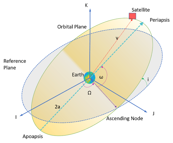
In this diagram, the orbital plane (yellow) intersects a reference plane (gray). For Earth-orbiting satellites, the reference plane is usually the I-J plane of the Geocentric Celestial Reference Frame (GCRF).
Two elements define the shape and size of the ellipse:
Eccentricity (e) — Shape of the ellipse, describing how elongated it is compared to a circle.
Semimajor axis (a) — Sum of the periapsis and apoapsis distances divided by two. Periapsis is the point at which an orbiting object is closest to the center of mass of the body it is orbiting. Apoapsis is the point at which an orbiting object is farthest away from the center of mass of the body it is orbiting. For classic two-body orbits, the semimajor axis is the distance between the centers of the bodies.
The next two elements define the orientation of the orbital plane in which the ellipse is embedded:
Inclination (i) — Vertical tilt of the ellipse with respect to the reference plane, measured at the ascending node (where the orbit passes upward through the reference plane, the green angle i in the diagram). Tilt angle is measured perpendicular to line of intersection between orbital plane and reference plane. Any three points on an ellipse will define the ellipse orbital plane.
Starting with an equatorial orbit, the orbital plane can be tilted up. The angle tilted up from the equator is referred to as the inclination angle, i. Since the center of the earth must always be in the orbital plane, the point in the orbit where the satellite passes the equator on its way up is referred to as the ascending node, and the point where the satellite passes the equator on the way down is the descending node. Drawing a line through these two points on the equator is what defines the line of nodes.
Right ascension of ascending node (Ω) — Horizontal orientation of the ascending node of the ellipse (where the orbit passes upward through the reference plane) with respect to the reference frame's I axis.
The rotation of the right ascension of the ascending node (RAAN) can be any number between 0 and 360°.
The remaining two elements are as follows:
Argument of periapsis (ω) — Orientation of the ellipse in the orbital plane, as an angle measured from the ascending node to the periapsis.
True Anomaly (v) — Position of the orbiting body along the ellipse at a specific time. The satellites position on the path is measured counter-clockwise from periapsis and is called the true anomaly, ν.
Aerospace Toolbox accepts Two Line Element (TLE) files as inputs to
satellite. To
download TLE files, visit the Space track website.
A two-line element set is a data format encoding a list of orbital elements of an Earth orbiting object for a given point in time, the epoch. Orbital elements parameters can be encoded as text in a number of formats. The most common of them is the NASA/NORAD "two-line elements" format. As commonly used today, each satellite gets three lines – one line containing the satellite’s name, followed by the standard two lines of elements.
Data for each satellite consists of three lines.
Satellite 1
1 25544U 98067A   04236.56031392  .00020137  00000-0  16538-3 0  9993
2 25544  51.6335 344.7760 0007976 126.2523 325.9359 15.70406856328906
Line 1 is a eleven-character satellite name.
Line 2 and 3 are the standard Two-Line element set format identical to that used by NORAD and NASA.
| Column | Description | Example |
|---|---|---|
| 1 | Line Number | 1 |
| 3 — 7 | Satellite Number | 25544 |
| 8 | Elset Classification | U |
| 10 — 17 | International Designator | 98067A |
| 19 — 32 | Element Set Epoch (UTC) | 04236.56031392 |
| 34 — 43 | First derivative of the Mean Motion with respect to time | .00020137 |
| 45 — 52 | Second derivative of the Mean Motion with respect to Time (decimal point assumed) | 00000-0 |
| 54 — 61 | BSTAR Drag Term. | 16538-3 |
| 63 | Element set type | 0 |
| 65 — 68 | Element number | 999 |
| 69 | Check Sum (Modulo 10) | 3 |
| Column | Description | Examples |
|---|---|---|
| 1 | Line Number of Element Data | 2 |
| 3 — 7 | Satellite Number | 25544 |
| 9 — 16 | Inclination [Degrees] | 51.6335 |
| 18 — 25 | Right Ascension of the Ascending Node [Degrees] | 344.7760 |
| 27 — 33 | Eccentricity (Leading decimal point assumed) | 0007976 |
| 35 — 42 | Argument of Perigee [Degrees] | 126.2523 |
| 44 — 51 | Mean Anomaly [Degrees] | 325.9359 |
| 53 — 63 | Mean Motion [Revs per day] | 15.70406856 |
| 64 — 68 | Revolution number at epoch [Revs] | 32890 |
| 69 | Check Sum (Modulo 10) | 6 |
Depending on the application and object orbit, the data derived from TLEs older than 30 days can become unreliable. Orbital positions can be calculated from TLEs through the SGP4 and SDP4 algorithms.
[1] “HSF - Orbital Elements.” Accessed November 30, 2020. https://spaceflight.nasa.gov/realdata/elements/graphs.html.
[2] “CelesTrak: ‘FAQs: Two-Line Element Set Format,” March 26, 2016. https://web.archive.org/web/20160326061740/http://celestrak.com/columns/v04n03/.
[1] Alignment of boundaries and region labels are a presentation of the feature provided by the data vendors and do not imply endorsement by MathWorks®.
