This example shows how to simulate the displacement of velocity sources and mass for different variant configurations using leaf type Variant Connector blocks. Variant Connector blocks allow you to activate or deactivate a set of components in the network during simulation without having to physically remove the components or exclude them from simulation.
To open the Variant Leaf Region in Mechanical System example model, type ssc_variant_connector_leaf_region in the MATLAB® Command Window.
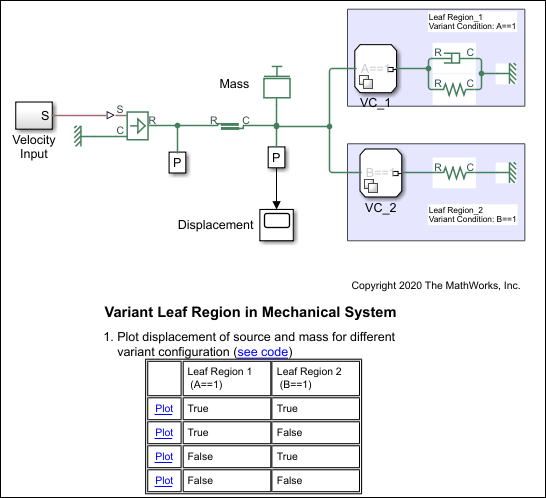
This model has two Variant Connector blocks, VC_1 and VC_2. These are leaf type Variant
Connector blocks. VC_1 has the variant condition A == 1 and VC_2 has the
variant condition B == 1.
During simulation, Simulink® computes the variant conditions associated with each leaf type Variant
Connector block. If the variant condition of a Variant Connector block evaluates to
true, all the physical components that are inside the leaf region of
that block become active. For example, if A == 1 evaluates to
true, the components inside LeafRegion_1 become active. If A
== 1 evaluates to false, the components inside LeafRegion_1
remain inactive.
The variant condition variables, A and B, are
defined in the PostLoadFcn callback. To view or modify the value of these
variables on the Modeling tab, select Model Settings > Model Properties. On the Callbacks tab, in the Model
callbacks pane, click PostLoadFcn. In this example, the
value of A = 1 and B = 2. The associated leaf region
activates based on these variables.
In the Model Properties window, set the value of
A to 1 and B to
2.
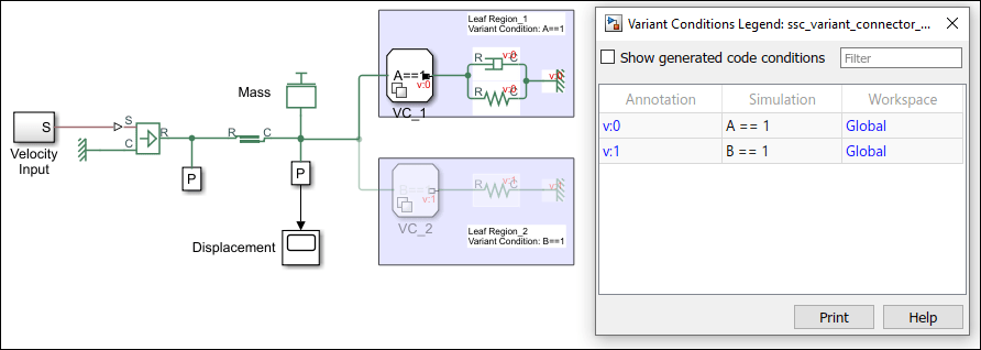
Click Run and see the variant conditions propagate from the Variant Connector blocks to the connected components.
To analyze the propagated variant conditions and the block activation state, on the Debug tab, select Information Overlays > Variant Legend. For more information on Variant Condition Legend, see Viewing Variant Conditions
A
          == 1
evaluates to true. The
components inside LeafRegion_1 become active.
B == 1 evaluates to false. The
components inside LeafRegion_2 become inactive.
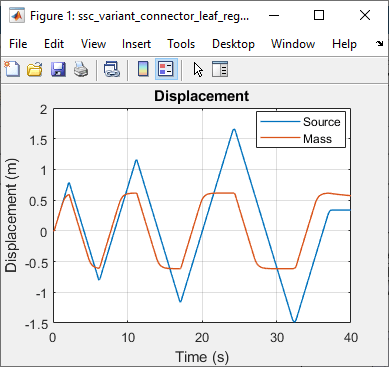
View the displacement of mass and the velocity source by clicking the
Plot link in the Variant Leaf Region in Mechanical
System table that corresponds to the condition, A ==
1 is true and B == 1 is
false.
In the Model Properties window, set the value of
A to 1 and B to
2, and then simulate the model.
Analyze the variant conditions and the block activation state.
A == 1 evaluates to false. The
components inside LeafRegion_1 become inactive.
B == 1 evaluates to true. The components
inside LeafRegion_2 become active
View the displacement of mass and the velocity source by clicking the
Plot link in the Variant Leaf Region in Mechanical
System table that corresponds to the condition, A==1
is false and B==1 is true.

Similarly, you can set the value of A and B to
0 and analyze how both the regions become inactive during
simulation.
