Use this section to learn how to use the FlightGear flight simulator and the Aerospace Blockset™ software to visualize your Simulink® aircraft models. If you have not yet installed FlightGear, see Flight Simulator Interface first.
Simulink Driven HL-20 Model in a Landing Flare at KSFC
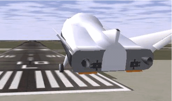
Before you can visualize your aircraft dynamics, you need to create or obtain an aircraft model file compatible with FlightGear. This section explains how to do this.
You have a competitive choice of over twelve 3-D geometry file formats supported by FlightGear.
Currently, the most popular 3-D geometry file format is the AC3D format, which has the suffix
*.ac. AC3D is a low-cost geometry editor available from
www.ac3d.org.
Aircraft models are contained in the FlightGearRoot/data/Aircraft/ folder
and subfolders. A complete aircraft model must contain a folder linked
through the required aircraft master file named model-set.xml.
All other model elements are optional. This is a partial list of the optional elements you can put in an aircraft data folder:
Vehicle objects and their shapes and colors
Vehicle objects' surface bitmaps
Variable geometry descriptions
Cockpit instrument 3-D models
Vehicle sounds to tie to events (e.g., engine, gear, wind noise)
Flight dynamics model
Simulator views
Submodels (independently movable items) associated with the vehicle
Model behavior reverts to defaults when these elements are not used. For example,
Default sound: no vehicle-related sounds are emitted.
Default instrument panel: no instruments are shown.
Models can contain some, all, or even none of the above elements. If you always run FlightGear from the cockpit view, the aircraft geometry is often secondary to the instrument geometries.
A how-to document for including optional elements is included in the FlightGear documentation at:
The flight dynamics model (FDM) specification is a required
element for an aircraft model. To set the Simulink software as
the source of the flight dynamics model data stream for a given geometry
model, you put this line in data/Aircraft/model/model-set.xml:
<flight-model>network</flight-model>
You can quickly build models from scratch by referencing instruments,
sounds, and other optional elements from existing FlightGear models.
Such models provide examples of geometry, dynamics, instruments, views,
and sounds. It is simple to copy an aircraft folder to a new name,
rename the model-set.xml file,
modify it for network flight dynamics, and then run FlightGear with
the –aircraft flag set to the name in model-set.xml.
Many existing 3-D aircraft geometry models are available for use with FlightGear. Visit the download area of https://www.flightgear.org to see some of the aircraft models available. Additional models can be obtained via Web search. Search key words such as “flight gear aircraft model” are a good starting point. Be sure to comply with copyrights when distributing these files.
When creating your own geometry files, keep in mind that your graphics card can efficiently render a limited number of surfaces. Some cards can efficiently render fewer than 1000 surfaces with bitmaps and specular reflections at the nominal rate of 30 frames per second. Other cards can easily render on the order of 10,000 surfaces.
If your performance slows while using a particular geometry, gauge the effect of geometric complexity on graphics performance by varying the number of aircraft model surfaces. An easy way to check this is to replace the full aircraft geometry file with a simple shape, such as a single triangle, then test FlightGear with this simpler geometry. If a geometry file is too complex for smooth display, use a 3-D geometry editor to simplify your model by reducing the number of surfaces in the geometry.
Once you have obtained, modified, or created an aircraft data file, you need to put it in the correct folder for FlightGear to access it.
To install a compatible model into FlightGear, use one of the following procedures. Choose the one appropriate for your platform. This section assumes that you have read Install and Start FlightGear.
If your platform is Windows:
Go to your installed FlightGear folder.
Open the data folder, then the Aircraft folder: \FlightGear\data\Aircraft\.
Make a subfolder model\
here for your aircraft data.
Put model-set.xml in
that subfolder, plus any other files needed.
It is common practice to make subdirectories for the vehicle
geometry files (\model\), instruments (\instruments\),
and sounds (\sounds\).
If your platform is Linux:
Go to your installed FlightGear directory.
Open the data directory, then the Aircraft directory: $FlightGearBaseDirectory/data/Aircraft/
Make a subdirectory model/
here for your aircraft data.
Put model-set.xml in
that subdirectory, plus any other files needed.
It is common practice to make subdirectories for the vehicle
geometry files (/model/), instruments (/instruments/),
and sounds (/sounds/).
If your platform is Mac:
Open a terminal.
Go to your installed FlightGear folder.
Open the data folder, then the Aircraft folder:
$FlightGearBaseDirectory/FlightGear.app/Contents/Resources/data/Aircraft/
Make a subfolder model/
here for your aircraft data.
Put model-set.xml in
that subfolder, plus any other files needed.
It is common practice to make subdirectories for the vehicle
geometry files (/model/), instruments (/instruments/),
and sounds (/sounds/).
This example illustrates how to prepare hinge line definitions for animated elements such as vehicle control surfaces and landing gear. To enable animation, each element must be a named entity in a geometry file. The resulting code forms part of the HL20 lifting body model presented in Run the HL-20 Example with FlightGear.
The standard body coordinates used in FlightGear geometry models form a right-handed system, rotated from the standard body coordinate system in Y by -180 degrees:
X = positive toward the back of the vehicle
Y = positive toward the right of the vehicle
Z = positive is up, e.g., wheels typically have the lowest Z values.
See About Aerospace Coordinate Systems for more details.
Find two points that lie on the desired named-object hinge line in body coordinates and write them down as XYZ triplets or put them into a MATLAB® calculation like this:
a = [2.98, 1.89, 0.53];
b = [3.54, 2.75, 1.46];
Calculate the difference between the points:
pdiff = b - a
pdiff =
	0.5600    0.8600    0.9300
The hinge point is either of the points in step 2 (or the midpoint as shown here):
mid = a + pdiff/2
mid =
	3.2600    2.3200    0.9950
Put the hinge point into the animation
scope in model-set.xml:
<center>
	<x-m>3.26</x-m>
	<y-m>2.32</y-m>
	<z-m>1.00</z-m>
</center>
Use the difference from step 3 to define the relative motion vector in the animation axis:
<axis>
	<x>0.56</x>
	<y>0.86</y>
	<z>0.93</z>
</axis>
Put these steps together to obtain the complete hinge line animation used in the HL20 example model:
<animation>
	<type>rotate</type>
	<object-name>RightAileron</object-name>
	<property>/surface-positions/right-aileron-pos-norm</property>
	<factor>30</factor>
	<offset-deg>0</offset-deg>
	<center>
		<x-m>3.26</x-m>
		<y-m>2.32</y-m>
		<z-m>1.00</z-m>
	</center>
	<axis>
		<x>0.56</x>
		<y>0.86</y>
		<z>0.93</z>
	</axis>
</animation>
To run a Simulink model of your aircraft and simultaneously
animate it in FlightGear with an aircraft data file model-set.xml,
you need to configure the aircraft data file and modify your Simulink model
with some new blocks.
These are the main steps to connecting and using FlightGear with the Simulink software:
Set the Flight Dynamics Model to Network in the Aircraft Data File explains how to create the network connection you need.
Obtain the Destination IP Address starts by determining the IP address of the computer running FlightGear.
Send Simulink Data to FlightGear shows how to add and connect interface and pace blocks to your Simulink model.
Create a FlightGear Run Script shows how to write a FlightGear run script compatible with your Simulink model.
Start FlightGear guides you through the final steps to making the Simulink software work with FlightGear.
Improve Performance helps you speed your model up.
Run FlightGear and Simulink Software on Different Computers explains how to connect a simulation from the Simulink software running on one computer to FlightGear running on another computer.
Be sure to:
Remove any pre-existing flight dynamics model (FDM) data from the aircraft data file.
Indicate in the aircraft data file that its FDM is streaming from the network by adding this line:
<flight-model>network</flight-model>
You need the destination IP address for your Simulink model to stream its flight data to FlightGear.
If you know your computer name, enter at the MATLAB command line:
java.net.InetAddress.getByName('www.mathworks.com')
If you are running FlightGear and the Simulink software on the same computer, get your computer name by entering at the MATLAB command line:
java.net.InetAddress.getLocalHost
If you are working in Windows, get your computer IP address by entering at the DOS prompt:
ipconfig /all
Examine the IP address entry in the resulting output. There is one entry per Ethernet device.
To start FlightGear with the desired initial conditions (location, date, time, weather, operating modes), it is best to create a run script by Use the Generate Run Script Block or Use the Interface Provided with FlightGear.
If you make separate run scripts for each model you intend to link to FlightGear and place them in separate directories, run the appropriate script from the MATLAB interface just before starting your Simulink model.
Use the Generate Run Script Block. The easiest way to create a run script is by using the Generate Run Script block. Use the following procedure:
Open the Flight Simulator Interfaces sublibrary.
Create a new Simulink model or open an existing model.
Drag a Generate Run Script block into the Simulink diagram.
Double-click the Generate Run Script block. Its dialog opens. Observe the three panes, FlightGear, Network, and File.
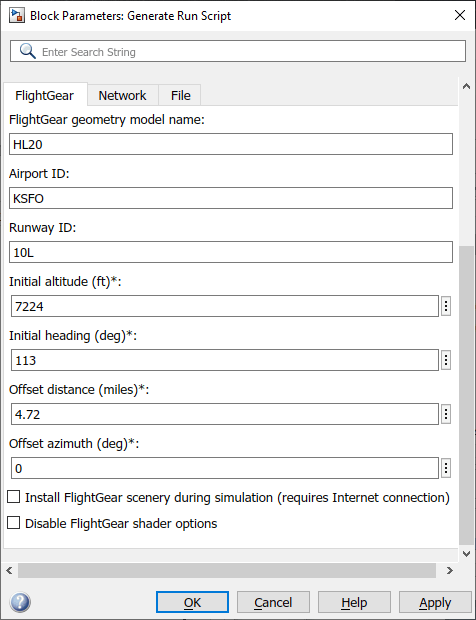
In the Output file name parameter of the File tab, type the name of the output file. This name should be the name of the command you want to use to start FlightGear with these initial parameters. Use the appropriate file extension:
| Platform | Extension |
|---|---|
| Windows® | .bat |
| Linux® and macOS | .sh |
For example, if your file name is runfg.bat,
use the runfg command to execute the run script
and start FlightGear.
In the FlightGear base directory parameter of the File tab, specify the name of your FlightGear installation folder.
In the FlightGear geometry model
name parameter of the File tab,
specify the name of the subfolder, in the
FlightGear/data/Aircraft
folder, containing the desired model geometry.
Specify the initial conditions as needed.
Click the Generate Script button at the top of the Parameters area.
The Aerospace Blockset software generates the run script, and saves it in your MATLAB working folder under the file name that you specified in the File > Output file name field.
Select or clear these check boxes and
To direct FlightGear to automatically install required scenery while the simulator is running — Select Install FlightGear scenery during simulation (requires Internet connection). For Windows systems, you may encounter an error message while launching FlightGear with this option enabled. For more information, see Install Additional FlightGear Scenery.
To disable FlightGear shader options — Select Disable FlightGear shader options.
Repeat steps 5 through 10 to generate other run scripts, if needed.
Click OK to close the dialog box. You do not need to save the Generate Run Script block with the Simulink model.
The Generate Run Script block saves the run script as a text file in your working folder. This is an example of the contents of a run script file:
>> cd C:\Applications\FlightGear-<your_FlightGear_version>
>> SET FG_ROOT=C:\Applications\FlightGear-<your_FlightGear_version>\data
>> cd \bin\
>> fgfs --aircraft=HL20 --fdm=network,localhost,5501,5502,5503
  --fog-fastest --disable-clouds --start-date-lat=2004:06:01:09:00:00
  --disable-sound --in-air --enable-freeze --airport=KSFO --runway=10L
  --altitude=7224 --heading=113 --offset-distance=4.72 --offset-azimuth=0
Use the Interface Provided with FlightGear. The FlightGear launcher GUI (part of FlightGear, not the Aerospace Blockset product) lets you build simple and advanced options into a visible FlightGear run command.
If your computer has enough computational power to run both the Simulink software and FlightGear at the same time, a simple way to start FlightGear on a Windows system is to create a MATLAB desktop button containing the following command to execute a run script like the one created above:
system('runfg &')
To create a desktop button:
In the MATLAB Command Window, select Shortcuts and click New Shortcut. The Shortcut Editor dialog opens.
Set the Label, Callback, Category, and Icon fields as shown in the following figure.
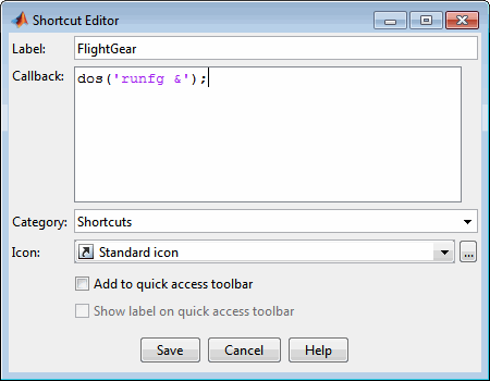
Click Save.
The FlightGear button appears
in your MATLAB desktop. If you click it, the output file, for
example runfg.bat, runs in the current folder.
Once you have completed the setup, start FlightGear and run your model:
Make sure your model is in a writable folder. Open the model, and update the diagram. This step ensures that any referenced block code is compiled and that the block diagram is compiled before running. Once you start FlightGear, it uses all available processor power while it is running.
Click the FlightGear button or run the FlightGear run script manually.
When FlightGear starts, it displays the initial view at the initial coordinates specified in the run script. If you are running the Simulink software and FlightGear on different computers, arrange to view the two displays at the same time.
Now begin the simulation and view the animation in FlightGear.
If your Simulink model is complex and cannot run at the aggregate rate needed for the visualization, you might need to
Use the Accelerator mode in Simulink (Perform Acceleration.)
Free up processor power by running the Simulink model on one computer and FlightGear on another computer. Use the Destination IP Address parameter of the Send net_fdm Packet to FlightGear block to specify the network address of the computer where FlightGear is running.
Simulate the Simulink model first, then save the resulting translations (x-axis, y-axis, z-axis) and positions (latitude, longitude, altitude), and use the FlightGear Animation object in Aerospace Toolbox to visualize this data.
Tip
If FlightGear uses more computer resources than you want, you
can change its scheduling priority to a lesser one. For example, see
commands like Windows start and Linux nice or
their equivalents.
It is possible to simulate an aerospace system in the Simulink environment on one computer (the source) and use its simulation output to animate FlightGear on another computer (the target). The steps are similar to those already explained, with certain modifications.
Obtain the IP address of the computer running FlightGear. See Obtain the Destination IP Address preceding.
Enter this target computer IP address in the Send net_fdm Packet to FlightGear block. See Send Simulink Data to FlightGear preceding.
Update the Generate Run Script block in your model with the target computer FlightGear base folder. Regenerate the run script to reflect the target computer separate identity.
See Create a FlightGear Run Script preceding.
Copy the generated run script to the target computer. Start FlightGear there. See Start FlightGear preceding.
If you want to also receive data from FlightGear, use the Receive net_ctrl Packet from FlightGear block. Enter the IP address of the computer running FlightGear in the Origin IP address parameter.
Update the run script for the receive data. Use the Generate Run Script block to regenerate the run script.
Start your Simulink model on the source computer. FlightGear running on the target displays the simulation motion.
The Aerospace Blockset software contains an example model of the HL-20 lifting body that uses the FlightGear interface and projects. This example illustrates many features of the Aerospace Blockset software. It also contains a Variant Subsystem block that you can use to specify the data source for the simulation. You might want to use the Variant Subsystem block to change the terrain data source or if you do not want to use FlightGear but still want to simulate the model.
To install and configure FlightGear before attempting to simulate this model, see Flight Simulator Interface. Also, before attempting to simulate this model, read Install and Start FlightGear.
Note
Step 2 of this example copies the preconfigured geometries for the HL-20
simulation from
projectroot\support to
FlightGear\data\Aircraft\. It
requires that you have system administrator privileges for your machine. If you
do not have these privileges, manually copy these files, depending on your
platform.
Copy the HL20 folder from
projectroot\support
folder to
FlightGear\data\Aircraft\
folder. This folder contains the preconfigured geometries for the
HL-20 simulation and HL20-set.xml. The file
projectroot\support\HL20\Models\HL20.xml
defines the geometry.
For Windows platforms, start the MATLAB app with administrator privileges. For example, in the Start menu, right click the MATLAB app, then select Run as administrator.
For more information, see Import Aircraft Models into FlightGear.
Copy the HL20 directory from
projectroot/support
directory to
$FlightGearBaseDirectory/data/Aircraft/
directory. This directory contains the preconfigured geometries for
the HL-20 simulation and HL20-set.xml. The file
projectroot/support/HL20/Models/HL20.xml
defines the geometry.
For more about this step, see Import Aircraft Models into FlightGear.
Copy the HL20 folder from
projectroot/support
folder to
$FlightGearBaseDirectory/FlightGear.app/Contents/Resources/data/Aircraft/
folder. This folder contains the preconfigured geometries for the
HL-20 simulation and HL20-set.xml. The file
projectroot/support/HL20/Models/HL20.xml
defines the geometry.
For more about this step, see Import Aircraft Models into FlightGear.
Start the MATLAB interface. Open the example either by entering asbhl20 in the
MATLAB Command Window or by finding the example entry (HL-20 with
FlightGear Interface) in the Aerospace Blockset Examples page. The project for the model starts and the model
opens.
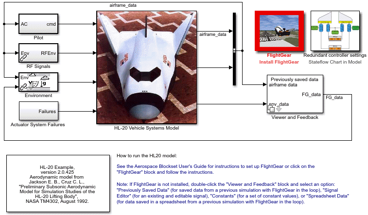
If this is your first time running FlightGear for this model, you need to create and run a customized FlightGear run script. You can do this with one of the following:
In the model, double-click the Install FlightGear block and follow the steps in the block. Initially, this block is red. As you follow the steps outlined in the block, the block mask changes.
To start FlightGear for the model, click Launch HL20 in FlightGear.
Now start the simulation and view the animation in FlightGear.
Note
With the FlightGear window in focus, press the V key to alternate between the different aircraft views: cockpit view, helicopter view, chase view, and so on.
You can send and receive data between a Simulink model and a running FlightGear Flight Simulator.
The easiest way to connect your model to FlightGear with the blockset is to use the FlightGear Preconfigured 6DoF Animation block:
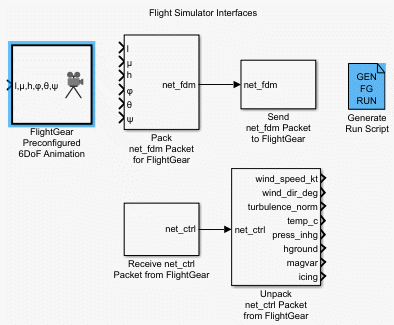
The FlightGear Preconfigured 6DoF Animation block is a subsystem containing the Pack net_fdm Packet for FlightGear and Send net_fdm Packet to FlightGear blocks:
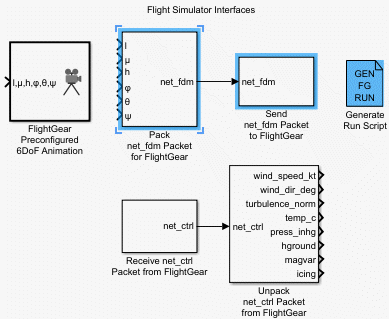
These blocks transmit data from a model to a FlightGear session. The blocks are separate for maximum flexibility and compatibility.
The Pack net_fdm Packet for FlightGear block formats a binary structure compatible with FlightGear from model inputs. In the default configuration, the block displays only the 6DoF ports, but you can configure the full FlightGear interface supporting more than 50 distinct signals from the block dialog box:

The Send net_fdm Packet to FlightGear block transmits this packet via UDP to the specified IP address and port where a FlightGear session awaits an incoming datastream. Use the IP address you found in Obtain the Destination IP Address.
The Simulation Pace block slows the simulation so that its aggregate run rate is 1 second of simulation time per second of clock time. You can also use it to specify other ratios of simulation time to clock time.
To increase the accuracy of your model simulation, you might want to send FlightGear environment variables to the Simulink model. Use the following blocks:

Receive net_ctrl Packet
from FlightGear — Receives a network control and environment
data packet net_ctrl from either the simulation
of a Simulink model in the FlightGear simulator, or from a FlightGear
session.
Unpack net_ctrl Packet from FlightGear — Unpacks net_ctrl variable packets received from FlightGear and makes them available for the Simulink environment.
Generate Run Script — Generates a customized FlightGear run script on the current platform.
For an example of how to use these blocks to send data to a Simulink model, see HL-20 Project with Optional FlightGear Interface.
These blocks use UDP to transfer data from FlightGear to the Simulink environment. Note the following:
When a host and target are Windows or Linux platforms, you can use any combination of Windows or Linux platforms for the host and target.
When a host or target is a Mac platform, use only Mac platforms for both the host and target.