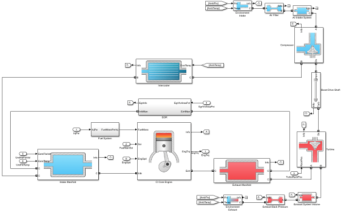
The compression-ignition (CI) engine dynamometer reference application represents a CI engine plant and controller connected to an AC dynamometer with a tailpipe emission analyzer. Using the reference application, you can calibrate, validate, and optimize the engine controller and plant model parameters before integrating the engine with the vehicle model. To create and open a working copy of the CI engine dynamometer reference application project, enter
By default, the reference application is configured with a 1.5–L CI dynamic engine.You can configure the reference application project for different dynamometer control modes. To implement the operating modes, the reference application uses variant subsystems.
This table summarizes the dynamometer tests.
| Test | Objective | Method | CI Engine Variant | |
|---|---|---|---|---|
| Mapped | Dynamic | |||
Execute Engine Mapping Experiment | Assess engine torque, fuel flow, and emission performance results using an existing engine controller calibration. | Dynamometer controller commands a series of engine speeds and torques to the engine controller. At each quasi-steady-state operating point, the experiment records the engine plant model output and the controller commands for the current calibration parameters. | ✓ | ✓ |
Execute Model Predictive Control Plant Model Experiment | Generate transient engine datasets for linear plant models useful for model predictive controllers. | Dynamometer controller commands engine speed and torque dynamically as a function of time using a pseudo random binary sequence. Experiment records the transient engine torque, temperature, airflow, and emission responses determined from linear dynamic plant model fitting via system identification. | ✓ | ✓ |
Recalibrate Controller | Match measured engine torque to commanded engine torque across engine operating range. | Dynamometer controller generates a feedforward fuel command table by matching the measured engine torque to the commanded engine torque across the engine operating range. | ✓ | |
Resize Engine and Recalibrate Controller | Match engine torque to desired engine power and number of cylinders. | Dynamometer resizes the dynamic engine and engine calibration parameters. Also, the dynamometer recalibrates the controller and mapped engine model to match the resized dynamic engine. | ✓ | ✓ |
Generate Mapped Engine from Spreadsheet | Generate a mapped engine calibration from a data spreadsheet. Update the mapped engine with the calibrated data. | Dynamometer uses the Model-Based Calibration Toolbox™ to fit data from a spreadsheet, generate calibrated tables, and update the mapped engine parameters. | ✓ | |
The reference application includes variant subsystems for mapped (steady-state) and dynamic 1.5–L CI engine systems with a variable geometry turbocharger (VGT). Using the CI engine project template, you can create your own CI engine variants.
| Objective | Engine Variant |
|---|---|
| Dynamic analysis, including manifold and turbocharger dynamics | Dynamic |
| Faster execution | Mapped |
CiEngineCore.slx contains the engine intake system, exhaust system, exhaust
gas recirculation (EGR), fuel system, core engine, and turbocharger subsystems.

CiMappedEngine.slx uses the Mapped
CI Engine block to look up power, air mass flow, fuel flow,
exhaust temperature, efficiency, and emission performance as functions
of engine speed and injected fuel mass.
The reference application contains a Performance Monitor block that you can use to plot steady-state and dynamic results. You can plot:
Steady-state results as a function of one or two variables.
Dynamic results using the Simulation Data Inspector.
CI Controller | CI Core Engine | Mapped CI Engine